Category Archives: Gadgets

Last updated by at .

Cord Panorama WiFi Internet Radio Player

Cord Panorama Internet Radio Player

Cord Panorama Internet Radio Player

We’ve been wanting a wifi internet radio player we could listen to around the house and perhaps take outside, plug in, and listen to out there. So, after a week or two of looking around online (and not really knowing what we needed) I made a spur of the moment decision and above you can see our new Cord Panorama WiFi Internet Radio/DAB+ Digital Radio / Media Player / FM Radio. We just bought it at 40% off of normal price from JB Hifi at the insanely good price of $132. It can play 100,000+ internet radio channels, stream media from a DLNA server, is a DAB+ digital radio receiver, and is a regular FM receiver too. And to top it all off it has an auxiliary input so you can plug in your iPod or other device and play music from that too. It has a bit of a retro look wood finish on the sides and top and a silver front panel with a black and blue OLED display. There’s a single speaker with a 7W digital amplifier, which it turns out is more than loud enough to fill our living area with music or to put it under our verandah and hear it while we’re in the backyard. There’s also a little remote which you can see below.

Cord Panorama Remote

Cord Panorama Remote

The device can work with a WiFi or wired connection and has a very simple setup wizard that allows you to enter your WiFi password pretty easily. Once setup the radio is controlled from either the front panel or remote. It operates in one of several modes (FM, DAB+, Media Streaming, Internet Radio, or AUX) each mode has slightly different menus and it’s own set of user selectable favourite stations. DAB+ and FM tuning were fairly effortless and intuitive. The media streaming mode detected our media server without a hassle and browsed quickly and easily through our media library and played our music perfectly.

Internet radio proved to be a little more problematic as the Cord unit kept timing out when attempting to retrieve a channel list from the internet. It started working after a day or so and allowed us to choose from many different Australian internet radio stations by genre. We could also search through the complete radio list allowing us to find our favourite stations easily. I’m not sure what the problem was with the network timeouts but I do note that the Cord Panorama has some sort of online integration with Wifi Radio Frontier site. And that site was down yesterday and this morning so I bet the two events are linked. The online integration allows the Cord Panorama users to find internet stations online and mark them as favourites and then have those stations downloaded to the radio unit. Pretty neat.

So what do I think of the Cord Panorama Internet Radio Player? I think it’s perfectly fine. The user interface is easy to understand, I didn’t have any problems with it and my partner has been using the radio from the front panel without issue. The front panel display is clear and useful and the tactile feel of the buttons and dials are quite nice. I’m even fond of the retro wood-grain finish. If I had anything bad to say I’d restrict it to the remote which is a bit small and fiddly and probably not that useful. But putting that to one side the Cord functions as advertised and pretty much flawlessly. The sound quality is good and it plays music from a variety of different sources exactly as advertised. And at the price we got it at I consider it to be something of a bargain. Highly recommended if you’re in the market for a wireless internet radio player.

Update December 9 2013

When I was having problems with the player connecting to internet radio stations I shot off an email to the distributor of the Cord Panorama in Australia (Volition Australia) asking them if they knew what the problem was. To be honest I wasn’t expecting a response as I’ve never had much luck contacting service departments by email before. But here we are at 10:00AM on a Monday morning and I got a response! Amazing service. Here’s what they had to say:

Mark,

Thanks for your enquiry.

It seems that Vtuner, the internet radio service used by panorama was down for a period of time over the weekend.
After checking this morning, it is up and running.
Let me know if you still have any problems.

Regards,

Michael Noorbergen
Technician

So, there’s your answer. The Cord Panorama uses the Vtuner website to get some data and it was down on the weekend.

Building a Garage Door Sensor with an Arduino Nano

The Problem

Our two car garage has a roller door on the front and back. The one on the front of the house is motorised and activated with a remote control. You cannot see if the front roller door is open from anywhere within our house so the only way to check if it is open is to walk outside and look. If you remember that is. The problem is that we do not want to go to bed and leave the front roller door on the garage open and we have done so a few times.

The Solution

Create some sort of sensor and indicator letting us know that the front roller door is open. The sensor should be reliable and the indicator should be obvious (especially when night has fallen) and not require us to walk outside to check on the status of the door. I’ve had an Arduino starter kit sitting on my desk for a while so (of course) I thought that the solution had to include an Arduino.

The Sensors

I wanted to detect if the door was up or down so this would require two sensors. Initially I was thinking along the lines of an ultrasonic detector but the cost of this was prohibitive as I needed two of them. In the end I settled on simple magnetic reed switches of the type you see in home security systems. One would be mounted to the door frame at the bottom and one at the top. A magnet would be fixed to the door to trigger the switches as the door moved up and down. The two door sensors with paired magnets were $5.

The Indicator

Initially I had thoughts of a two unit system. One sender unit mounted on the garage door and a receiver unit that sat inside with an indicator light with RF comms using one of the many different types of Arduino RF shields. But this was complete overkil so in the end I settled on 2 colour high intensity 3 watt LED that could be mounted outside our kitchen window and be driven by a cable. The LED module would need to be driven by a decent constant current power supply so I bought a couple of 330mA units at the same time. These PSU’s could be driven by a 0-5V PWM (pulse width modulated) signal to adjust the intensity of the driven LED. The LED module was $3, a heatsink to mount the LED on was $3, and the PSU’s were $9 each. A transparent poly-carbonate box to install the LED in was $9. The cable ended up being some 8 core alarm cable that cost about a dollar a meter and I used some 6 pin audio plugs for each end. Total cost for the cable was around $20 or so.

The Arduino

My Arduino kit contains a Arduino UNO clone. This was bigger than I wanted so I settled on a cloned Arduino Nano from eBay which was about $10. This had the digital inputs I wanted, more than enough memory to hold the simple sketch I’d write, could be run from a 12V DC plug pack, and the PWM outputs I’d need.

Enclosure and Breadboard

The enclosure would need to hold the Arduino Nano, the two LED PSU’s, and a small breadboard. It would also need to take the wires from the door sensors, have a female socket to take 12V and a female connector to plug our LED cable into. The breadboard was used to make a circuit that would ground out the sensor signals and route 3.3V to the sensors and 12V to the LED power supplies. All connections from the circuit to the Arduino and the Arduino to the power supply were done via connectors and cables I had laying around from old PC builds. Total cost of the enclosure and assorted components (and a 2A 12V DC plug pack) ran out to about $40.

Build Problems

One of the LED PSU’s was DOA so I settled on running just one of the LED colours. I chose to indicate different door states by flashing the LED at different rates. A second problem was that the roller door frame was significantly out of square and the magnets supplied with the reed switches were not strong enough to trigger the switches. I solved this by purchasing a rare earth magnet and gluing it to the roller door (cost was $12).

Arduino Code

I decided on a simple state engine for the code to run my indicator light. The first state was door down. In this state the Arduino was in a “door closed sleep” state waiting for an interrupt from the bottom door sensor. When the state of this sensor changed the Arduino would wake and enter a “door in transition” state and flash the LED rapidly. When the top sensor triggered the door would enter a third “door up” state and pulse the light slowly. When the roller door was lowered the Arduino would enter the “door in transition” state again and stay that way until the door closed and the bottom sensor was triggered. The Arduino would now enter a “door closed indicator” state and leave the LED on for 10 seconds before entering the “door closed sleep” state. Here’s the Arduino sketch I came up with to accomplish this:

#include <avr/interrupt.h>
#include <avr/power.h>
#include <avr/sleep.h>


const int blueLED = 3;
const int ledBrightness=50;
const int doorDownSensor=2;
const int doorUpSensor=4;
int doorDownSensorState=0;
int doorUpSensorState=0;
int oldDoorUpSensorState=0;
int oldDoorDownSensorState=0;
int tmpState=0;
int i=0;
int pulseStep=1;
int pulseBrightness=0;
unsigned long blueLEDStartTime;
String tmpString;

unsigned long endLastPulse;
unsigned long pulseDelay=3000;

void setup() {
  // put your setup code here, to run once:
  pinMode(blueLED,OUTPUT);
  pinMode(doorDownSensor,INPUT);
  pinMode(doorUpSensor,INPUT);
  
  Serial.begin(9600);
}

void loop() {
  tmpState=digitalRead(doorDownSensor);
  
  
  if (tmpState==HIGH)
    tmpString="HIGH ";
  else
    tmpString="LOW ";  

  if (tmpState != oldDoorDownSensorState)
  {
    doorDownSensorState=1-doorDownSensorState;
    delay(50);
    if (doorDownSensorState==1)
    {
      blueLEDStartTime=millis();  
    }
  }
  oldDoorDownSensorState=doorDownSensorState;
  
  tmpState=digitalRead(doorUpSensor);

  if (tmpState==HIGH)
    tmpString+="HIGH ";
  else
    tmpString+="LOW "; 
    
  if (tmpState != oldDoorUpSensorState)
  {
    doorUpSensorState=1-doorUpSensorState;
    delay(50);
  }
  oldDoorUpSensorState=doorUpSensorState;  
  
  tmpString+="DOWN_STATE::";
  tmpString+=doorDownSensorState;
  tmpString+=" UP_STATE::";
  tmpString+=doorUpSensorState; 
  Serial.println(tmpString); 
    
  if (doorDownSensorState==1)
  {
    if ((millis()-blueLEDStartTime)<=10000)
      analogWrite(blueLED,ledBrightness); 
    else
    {
      analogWrite(blueLED,0);
      sleepNow();
    }
  }

  
  if (doorUpSensorState==1)
  {
    if (endLastPulse==0 || (millis()-endLastPulse)>pulseDelay)
    {
      pulseBrightness+=pulseStep;
      if (pulseBrightness<0)
      {
        pulseBrightness=0;
        pulseStep=-1*pulseStep; 
        endLastPulse=millis();
      }
      if (pulseBrightness>ledBrightness)
      {
        pulseBrightness=ledBrightness;
        pulseStep=-1*pulseStep; 
      }      
      analogWrite(blueLED,pulseBrightness);
      delay(25);
    }

  }
  else
  {
    endLastPulse=0; 
  }

  
  if (doorDownSensorState!=1 && doorUpSensorState!=1)
  {
    if ((millis() % 1000)<500)
      analogWrite(blueLED,ledBrightness);    
    else
      analogWrite(blueLED,0);        
  }

  
}

void sleepNow()
{
    // Set pin 2 as interrupt and attach handler:
    attachInterrupt(0, pinInterrupt, LOW);
    delay(100);
    //
    // Choose our preferred sleep mode:
    set_sleep_mode(SLEEP_MODE_PWR_DOWN);
    //
    // Set sleep enable (SE) bit:
    sleep_enable();
    //
    // Put the device to sleep:
    sleep_mode();
    //
    // Upon waking up, sketch continues from this point.
    sleep_disable();
}

void pinInterrupt(void)
{
  detachInterrupt(0);
}

There’s a couple of things to note here. First, the Nano only has interrupts on IO pins 2 and 3 so the bottom door sensor had to be on one of these pins. I used pin 2 which is interrupt 0. Also, I wanted to drive the LED power supply with a PWM signal so I had to use one of the PWM capable outputs, in my case I used pin 3.

I developed this code on my Arduino UNO with the circuit mocked up on a spring breadboard that came with my starters kit. Flashing the code to the Nano was troublesome because it turns out that the Nano I bought had a problem with the serial chip (UART) and just wouldn’t talk to my computer. After much googling I just needed to download and install an older driver for the USB/Serial driver on my PC and suddenly I could talk to the Nano.

Installation

The hardware mounted up easily enough. The reed switches included adhesive and stuck well enough to the door frame once I had cleaned the metal with some acetone. The door magnet was put in place with some cyano acrylate glue. Cabling from the sensors to the control box was cheap two core cable and the control box was mounted to the wall with some wall plugs I had lying around. A friend of mine helped me route the LED cable through my roof cavity and the LED box was stuck to one of the beams of the verandah outside our kitchen window.

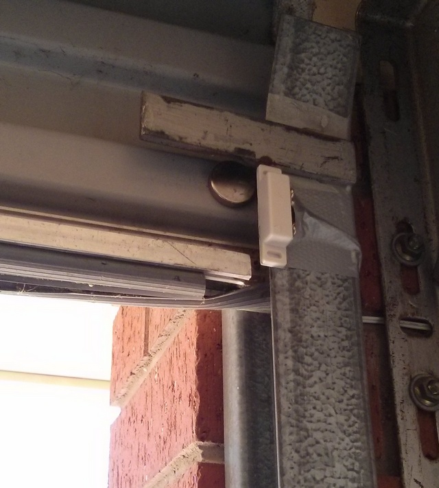
Here’s one of the reed switches mounted to the top of the door frame. You can see the rare earth magnet (the silver disk) on the door itself.

Reed Sensor and Magnet

Reed Sensor and Magnet

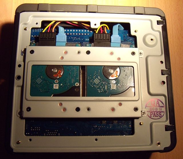
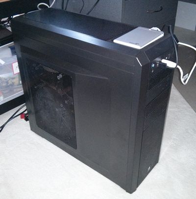
And here’s the control box containing the Arduino Nano, home made circuit, and one of the constant current power supplies that drive the LED. The 12V power goes in via the plug at the bottom left while the cable coming out the top right goes into the roof cavity and drives the LED.
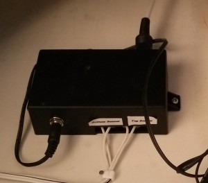
Arduino Enclosure

Arduino Enclosure

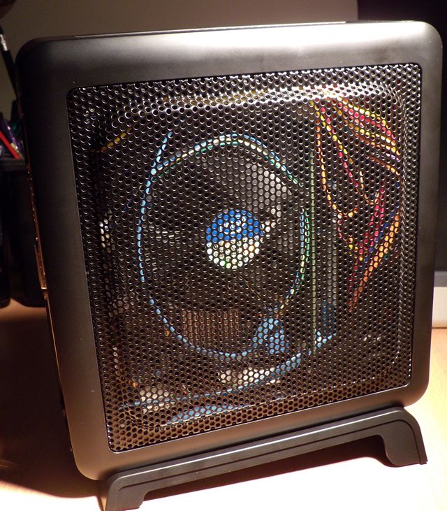
Finally, here’s the LED box mounted to a beam on our verandah. It’s the blue thing in the middle of the picture. You can see the cable running across to the top of the beam it’s mounted on.
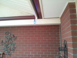
LED Enclosure

LED Enclosure

Here’s what it looks like in operation:

Having Trouble Viewing Media on Your Sony Bravia TV?

If you’ve got a latish model internet-enabled Sony TV (we have a Sony Bravia KDL40HX750 TV) then you may know it can display media streamed from a compliant DLNA server. If you know this you probably also know that the Sony TV’s can be very picky about what media formats (specifically movies) they will and wont play. I’ve had some luck converting movies to different file formats but even with this solution I’d pretty much given up on watching streamed movies on the TV because it was just all too hard. So I’d been resorting to using my five year old WD Live Media Player with an external HDD plugged into it.

However, I’ve hit on a solution that has allowed me to watch almost any movie in any format on our Sony TV. I’ve setup a DLNA media server and downloaded the great app Bubble UPNP to our Nexus 7 tablet. Once the app is installed it’s just a matter of connecting it to our media server, choosing a movie to play and selecting our Sony TV as a rendering device. Once that is done and I press PLAY in the app by the magic of smoke and mirrors the movie starts playing on the TV. Fabulous.

Turning Your Headless Linux Machine into a DLNA Media Server

We have had a Sony Bravia KDL40HX750 TV for a while now. It’s a great TV and can stream media from a compliant DLNA media server. I was doing this with Windows Media Player from my dev PC but given that my dev machine is usually turned off after 9PM it wasn’t used much. So, given that my My mini-ITX file server had been running nicely for a week or so I figured it could become the new media server for the house. Here’s how I got it working.

1. Mount an External HDD

The first problem was to mount an external USB disk drive to hold the media. And I wanted it to mount to the same point every time it was unplugged and plugged back in. This was fairly simple. Firstly, we need to work out the UUID of the USB drive we want to use. Run:

sudo blkid

And you should see something like that shown below. Our USB drive is on the bottom line,

/dev/md1: UUID="a20f7307-fb20-4c92-95d2-db222778af8f" TYPE="swap"
/dev/md0: UUID="c4c0ea5f-0613-4acc-8fa5-4d5968802771" TYPE="ext4"
/dev/sdc1: UUID="AE884FDE884FA425" TYPE="ntfs"

Once you know the UUID open up /etc/fstab in your text editor of choice and add an entry that looks something like this:

UUID=AE884FDE884FA425 /media/mediadrive ntfs defaults 0 0

Save those changes. Then create a mount point for your mediadrive using something like:

sudo mkdir /media/mediadrive/

Then reboot your machine and you should find that fstab mounts your USB drive to /media/mediadrive

2. Install and configure minidlna

There’s a number of DLNA compliant media servers for Linux. I chose minidlna because it was small and seemed to just work. Install it with:

sudo apt-get install minidlna

Then open the minidlna.conf file with:

sudo nano /etc/minidlna.conf

And configure to suit. I left most settings as is but you’ll need to set the path to your media drive, the network interface, and give your media server a name for devices to use when they connect to it. Here’s what those settings look like:

media_dir=/media/mediadrive
network_interface=p4p1
listening_ip=192.168.2.3
friendly_name=EinsteinJR

I note that there’s a web interface to manage minidlna but I haven’t taken a look at that.

Save the config changes and then restart minidlna with:

sudo service minidlna restart

3. Refresh Your Media LIbrary

By default minidlna refreshes your medial library every 895 seconds (controlled by the notify_interval setting in the conf file). However, if you’re impatient you can force a refresh with:

sudo minidlna -R
sudo service minidlna restart

Alternatively you can force the database refresh using:

sudo service minidlna force-reload

Once your library is refreshed you should see your new server available from your media device and be able to view your movies or listen to your music.

Building a New Mini File Server

So I completely lost confidence in our Mac Mini after the power surge issues and decided to build a new file server. I wanted something small and quiet built from standard components that would run Ubuntu server. I spent some time looking about and decided on the following build:

Case : Antec Mini ISK110 Vesa
CPU: Intel G2030 Pentium
CPU Cooler: Stock (if possible)
RAM: 4GB Generic
Motherboard: Gigabyte GA-H61N-D2V
Drives: 2x500GB 5400RPM 2.5″ laptop drives

Total cost was around AU$400. I ordered the case from an online vendor, the motherboard from eBay and the rest of the components were sourced from MSY Computers.

Gigabyte GA-H61N-D2V Motherboard

Gigabyte GA-H61N-D2V Motherboard

The mini-ITX format motherboard from Gigabyte (see above) shipped with a back plate and two HDMI cables. It has USB ports via the rear panel, has two RAM slots, 4 on-board SATA3 ports and supports any LGA1155 pin Intel PC. If the installed CPU has a GPU then there’s an available HDMI port too.

Intel G2030 Pentium and Stock Cooler

Intel G2030 Pentium and Stock Cooler

I chose the G2030 Pentium from Intel because it has on-board video, two cores, and a 55W thermal design load. And it was cheap. This is a file server so I didn’t see the need for excess CPU cycles. There’s a mobile version of the G2030 that has a TDP of 35W but that was more expensive and not available locally.

Motherboard with Installed CPU and RAM

Motherboard with Installed CPU and RAM

As I usually do I installed the CPU, fan, and RAM to the motherboard before the board went into the case. No issues here, everything went in smoothly. I was hoping the stock fan would fit in the small Antec case. If not I would have to purchase a low profile HSF unit like this Noctua unit. It turns out the stock fan DID fit and is very quiet at low RPM.

Antec ISK 110 Mini-ITX Case

Antec ISK 110 Mini-ITX Case

Above you can see the Antec case I chose. It comes with a 90W external power supply, has 4 USB2.0 front panel ports, has space for two 2.5″ drives internally and supports the mini-ITX motherboard format. It comes with a desk stand (which you can see on the right) and a VESA bracket so you could bolt it to the back of a monitor or TV. Ideal if you wanted a small format media PC or all-in-on PC solution. The case itself is about the size of a large format paperback novel. Quite a bit bigger than a Mac Mini but still very small.

Antec ISK 110 Mini-ITX Case Internals

Antec ISK 110 Mini-ITX Case Internals

Here’s the guts of the case. The cables on the right are all for the front panel. At the top is the PSU.

Motherboard Installed

Motherboard Installed

The motherboard went into the case without too much trouble. The front panel cables are stiff and impede on the area where the mother board wants to sit. So they need some bending to move them out of the way. Also, the back panel insert needs to be removed to fit the motherboard but it’s easily replaced with the back panel that shipped with the motherboard.

Back Panel

Back Panel

Here’s the back panel. The usual array of connections are available.

HDD Cage

HDD Cage

The cage for the two internal HDD’s is on the back of the case. In this image the cage is in the center of the image and attached by a screw at each corner. It was simply a matter of removing the cage and applying the included adhesive anti-vibration pads. You can see what this looks like below.

HDD Cage with Anti Vibration Pads

HDD Cage with Anti Vibration Pads

My two 2.5″ hard disks then simply screwed into the cage with the screws that were included with the case. The only issue here was to ensure that the drives were aligned correctly so that power cables and SATA cables could be routed easily to the drives.

Hard Drives in Cage

Hard Drives in Cage

Once I’d screwed the cage back to the case and routed the SATA cables and power cables from the front of the setup looked very neat indeed. You can see what it looked like below. My only comment is that you’ll want two SATA cables with 90 degree bends on one end to make the job of connecting up the drives as easy as possible.

Hard Drive Installation Completed

Hard Drive Installation Completed

The final step in the process meant flipping the case back over and finishing off the cabling to the motherboard. The ATX power supply harness was very rigid and needed some work to get it bent to the shape I wanted. Once I’d done that the rest of the cabling was easy enough. I managed to tuck away a lot of the cables in the edge of the case out of sight to neaten things up. You can see the final result below. One comment I would make here is that while the Gigabyte motherboard does have a PCI-E slot I would be dumbfounded if you could fit a card in this case. There just doesn’t seem to be enough clearance.

Cabling Complete

Cabling Complete

And here’s the final product with the sides of the case back on. Lot’s of ventilation means that it can run with the CPU fan idling away silently at 900RPM or so and there hasn’t been a need for a case fan at all. Admittedly it’s winter here and with room temperatures of less than 20 degrees Centigrade the CPU temperature has been sitting at about 40 degrees for several days now. I can wind the fan speeds up during the hotter parts of the year if needed.

Completed Teeny Tiny Computer

Completed Teeny Tiny Computer

I installed Ubuntu Server 13.04 on the machine and setup the disks in a RAID1 configuration. Installation was very smooth and without issue. I even had time to do a few experiments removing the disks to make sure the computer still booted and I could recover data from the degraded array.

New Tablet – Asus Google Nexus 7

Google / Asus Nexus 7

Google / Asus Nexus 7

I’d been wanting another tablet for a while (I’ve had an iPad 1 for several years) and based on the good experiences I’ve had with my Google Nexus 4 phone I was quite happy to try out the equivalent Google tablet option. It just so happens that last week I walked past an electronics store with a hand-written sign on the door “Daily Special – Nexus 7 32GB $199 normally $279”. If ever a sign was a sign that I should adhere to the advice of a sign then that sign was it. In I went and bought myself a Google Nexus 7, manufactured by Asus and running Android 4.2.2 (Jelly Bean). You can see what the Nexus 7 looks like above. There’s a camera in there, but it is only 1.2 mega pixels so don’t expect anything special from it. The back of the unit is covered in a textured plastic material (see below) emblazoned with the Nexus and Asus logos.

Back of the Nexus 7

Back of the Nexus 7

Given that Android uses soft buttons at the bottom of the display the actual hardware controls are somewhat sparse. Just two buttons, a volume rocker and a power switch (see below) can be found at the top right side of the unit.

Volume / Power Buttons

Volume / Power Buttons

At the bottom of the Nexus you can find a mini USB port, a headphone jack and just round the back a cut-out for the internal speaker. You can see these below.

Headphones / USB / Speaker

Headphones / USB / Speaker

OK. So what’s it like? My first impressions are that it’s a much more manageable size that a 10″ tablet (like an iPad). I can mostly use the Nexus 7 one-handed and it’s quite comfortable to do so. The textured reverse of the unit is nice to grip onto and doesn’t get tiring if you’re using it for an extended period. Visually it’s inoffensive but if I had one comment it’s that the 7″ screen looks rather skimpy inside what is a wider than expected black frame. But I suppose there has to be somewhere to hang onto it!

Given that the tablet uses the same OS as my Nexus phone I settled into how the tablet works almost instantly. There’s some very minor differences in the way the Google app icons are grouped and the way the tablet information slider that is always available at the top right of the screen works. And the wider screen allows for more app icons across the bottom of the screen (they are lined up the side of the screen in landscape mode). In any event, the differences are minor and anyone who has used a device with a fairly vanilla install of Android 4.2.2 will be right at home. The software itself is quite responsive so whatever processor is in the Nexus is up to the job. If I had one quibble it’s that things just don’t seem quite as polished as they are on my 4 year old iPad. Scrolling isn’t quite as smooth, sometimes I need to poke at on-screen buttons more than once, and the location of the settings button in various apps seems to change with little rhyme or reason. Clearly the people looking after iOS run a much more rigid development system than the Android people.

There’s no native flash support in Android 4.2.2 so if you’re wanting to watch videos online you’re going to need to download a browser with Flash enabled natively (like Dolphin) or sideload Flash and install Firefox. But, even when I’d done that Flash support was flaky. For example, I could get SBS On Demand working but still haven’t had any luck with ABC iView.

I’ve had this unit for a week now and I’m happy with it at the price I paid. If I’d paid full asking price I’d be much less impressed (actually I wouldn’t have it at all). Recent media reports suggest tablets of this size are likely to see price drops in the near future so I’d hold out to get a Nexus 7 at a discounted price if possible. It’s ideal if you’re after a small form tablet, want to keep away from the Evil Apple Empire, and don’t want a tablet loaded down with pre-installed crap software. So what do I think of the Google Nexus 7? At the price, it’s hard not to like it. Go get one.

New IP Phone – Gigaset C610A IP

Our ISP offers a free VOIP service along with providing access to (pretty crappy) ADSL. We had an old VOIP box (an Open Networks 812L) sitting in a box that used to work but despite my best efforts I’ve been unable to get it working again. Cue my recent power problems and once I’d sorted those out I thought it was time to have one more go getting the 812L to work.

A couple of hours later and I’d failed. No matter what I tried I just couldn’t get into the web management console for the device because I couldn’t work out what the IP address of the device was. I dimly remember that the device had an in-built DHCP server so I even plugged it into a laptop in the hope it would give the laptop an IP address. Fail. Installed a port scanner and tried to determine the IP address that way. Fail. OK, pressed the hard reset button on the 812L…..and that did exactly nothing. So I gave up in disgust and consigned the unit to the bin.

The next step was to spend 20 minutes reading some VOIP oriented forums and looking at the IP phones that my ISP supported. Based on what I’d read and what my ISP supported I decided on a Siemens Gigaset C610A IP. This is a DECT IP phone with a built in answering machine (that’s what the A in the model number means). It allows you to use two different VOIP lines AND the standard analog line. I bought one for about $190 (can anyone say Australian rip-off….they can be had for half this price in the USA) and a few days later the phone showed up. Here’s what it looks like on my desk:

The Siemens Gigaphone C610A IP Phone

The Siemens Gigaphone C610A IP Phone

The box the machine came in included the handset, the charging base for the handset, the base unit, a belt clip for the handset, some rechargeable AA batteries, two power units, a skimpy instruction manual and a CD of software they never expect anyone to use. The base unit plugs into a router and into the phone line. The handset / charger can sit anywhere I’d imagine. Setting up the unit was a doddle. Once I’d plugged the base unit into my router it grabbed an IP address and informed me via the handset that it wanted to download a firmware update. This was done in a few minutes. Then it was simply a matter of logging into the web management console of the phone and entering my ISP assigned IP phone number and passwords. 5 minutes later it was all done and I could make calls. The voice quality of which were excellent.

The handset seems to be nicely designed as does the software it runs. The handset offers much online integration to services like eBay, Facebook and news/weather services. I am not sure how much use these would be with the titchy little colour screen but I guess some people *might* use them. The unit also has the usual myriad selections for ringtones and message tones. There’s also the capability to assign different tones depending on the phone call source (for example from different VOIP lines and the analog phone lines). I’ve not spent too much time playing with this side of things though.

Given my recent run of bad luck with hardware this phone has been a pleasant surprise. I felt cheated somehow that it only took me 10 minutes to get it working and was sure it was going to be harder. But it wasn’t. So, the Gigaset C610A IP phone is, for ease of setup alone, highly recommended.

New UPS – APC Back-UPS ES700

APC UPS ES700

APC UPS ES700

In light of my recent power surge woes I’ve gone ahead and bought a UPS. The chosen unit is an APC 700VA ES700. This unit comes with 8 plugs, 4 of which are surge protected and can run from battery power. The other four are just surge protected. I chose this unit because the capacity of 700VA should be enough to keep my file server, my router, my main PC and one monitor active for several minutes in the case of a power interruption. Long enough for me to save my work and gracefully shut down my file server and PC. The battery in the UPS is user-replaceable too which is handy a few years down the track when the battery is shot.

The unit was around $150 and weighs about 8 kilograms. It’s small enough to sit behind my monitors for easy access. The only real set up required was to connect the terminal for the battery and to charge it for 16 hours before usage. Once I’d done that I plugged my PC, a monitor, the router and file server into the UPS enabled plugs. The surge protected plugs were connected to a couple of powerboards that run the rest of my monitors, my partner’s PC, and the network printer. I can verify that the UPS works as advertised because the power happened to flicker on and off not 12 hours after I inserted it into my systems. The unit doesn’t make any noise when operating normally but I did note a hum when the unit was operating from the batter.

There’s a feature of the APC ES-700 that I didn’t use. One of the UPS enabled powerpoints can act as a master and three of the surge protected points can slave from this. When the master is off all power to the slaved powerpoints is stopped, allowing users to save on stand by current draw. This could be ideal if you wanted to use the UPS in your home theater. You could (for example) assign your TV as the master and slave your PVR and hifi system off of that. The documentation also mentions being able to tune the UPS for the current draw of your master device. Seems like a handy feature.

APC UPS ES700 In Use

APC UPS ES700 In Use

Power Surges, Dead Macs, and VirtualBox

Power Surges

It’s been something of a disaster here in the last 10 days. Things were going swimmingly until last Friday when the power flickered on and off. Normal the quality of power supply here is excellent and this is the first time the power had gone off in a while. All of my hardware (or so I thought) is plugged into surge protected power boards so I wasn’t too worried. My main PC came back up no problems as did the laptop, modem, network switch and everything else. But I couldn’t get a connection to the internet from any computer.

Dead Router

Several ADSL router reboots later and with the help of an old laptop I’d isolated the problem to being in my ADSL Modem/Router. It just failed to connect to the internet. OK, dead modem, At that point I was a bit baffled why it would be dead because the modem is plugged into a high quality surge stopping power board. Off to the computer shop I go and 30 minutes later come back with a Billion 7800 NXL router. I picked it because of the dual band WiFi and the capability of running an external USB device. Got that home, connected it to the ‘net without issue and then plugged the network cable from my network switch to the modem. And bang, down went the modem. Uh-oh. Well it turns out the network switch wasn’t plugged into a surge protector. So it was dead and doing weird things to anything connected to it. So, I pulled the switch out of the network and connected the various PC’s directly to the modem and everything came back online. Yay. Or not.

The Dead Mac Mini

The Dead Mac Mini

Dead Mac Mini

At this point I’d plugged in the Mac Mini Server with dual RAID disks which acts as a simple network file server and also runs a series of CRON jobs to perform rsync driven backups from various servers around the internet that I look after. The Mac had appeared to boot up OK. I say appeared because I don’t actually run this machine with a monitor. In fact the last time I had a monitor plugged into it was two years ago. The only way I can tell it’s alive is by a single LED on the front and whether or not I could access the shared directories we use every day. It turns out I couldn’t access anything from it. I couldn’t open a PuTTy session with it either. Anyway, to cut a long story short I had to find a spare monitor and keyboard and mouse to plug into it and see if I could log into the OS via the GUI. Turns out the Mac wouldn’t boot up reliably, would occasionally let me log in and then freeze, or would just freeze and the opening login screen. Bugger that’s dead too.

Emergency Remote Backups

At this stage I was getting nervous because there were no backups being done of anything anymore. I quickly installed an Ubuntu virtual machine in Virtual Box and got some jobs going to rsync my files down from various remote servers in the USA. There was a bit of a hassle getting the Ubuntu client to connect to shared drives on the Windows 7 Host but found this web page to be very helpful. Basically I created a directory on the Ubuntu client using:

sudo mkdir /media/share-name

And then mounted the VirtualBox shared folder using:

sudo mount -f vboxsf shared-folder-name /media/shared-name

I wanted the mount to be persistent and I couldn’t make heads or tails of solutions I’d found that suggested adding entries to /etc/fstab. So I ended up creating a shell script with this in it:

sudo mount -f vboxsf shared-folder-name /media/shared-name
return 0

Then I made the script executable using:

sudo chmod +x script.sh

Then added an entry to my /etc/rs.local file with something like this:

/path/to/script.sh

Once that was done my lovely VirtualBox shared folders were available to my various cron jobs when I started up my Ubuntu VM. Once the CRON jobs were run at least I’d have up-to-date backups on a disk in my office.

The New PC

The New PC

A New PC

If there’s been one bit of luck in this whole episode it’s that I happened to have the makings of a new PC sitting in boxes in my office when the power surge happened. I’d been planning on upgrading my main PC and had bought the components in preparation of a leisurely build and test cycle before I transitioned to the new machine. Clearly there was a rush on and I needed the PC to act as a primary shared file server and to be running back scripts rather than my main development PC. So one very late Friday night later I had the machine built and Windows 7×64 Pro installed on it.

I don’t really want to talk to much about the specs of the PC because, well, it bores me. But if you want to know it’s an i5-3570 (my first Intel machine) on a ASUS motherboard with 16GB of ram, a Gigabyte 7850 video card, a 256GB SSD boot drive and a WD Green 2TB hard disk. I was primarily interested in keeping the machine quiet so there’s a high end modular PSU in the machine, a Noctua HSF combination with a low speed 150mm fan and it’s all sitting in a huge well ventilated Corsair Carbide 500R case. The machine seems to work well, is very quiet, and operates much cooler than the AMD based machine I’m using right now. I’ve installed VirtualBox on the new PC too and have Ubuntu running in it performing all of the required backup tasks that I had running on my main PC for just a day or two. The new PC is also acting as a central file repository on my network and is keeping synced copies of all critical files on several external USB drives. This setup will have to tide me over until the Mac returns.

Lessons Learned

This whole disaster could have been avoided if I’d just taken care with how I’d had the network switch had been plugged into the power. I suspect it wiped out the Mac Mini and the old ADSL modem via network cables. I’m just lucky it didn’t take out my main PC and laptop as well. We had minimal data loss because my last backup was just a few hours old. All backups here are automatic and the effort I put into the system a while back paid off in spades. Most of my time has been lost building the new PC, getting a grip on Ubuntu and how it works with VirtualBox, and running backwards and forwards to computer shops and repairers. I’ve also realised I needed a real UPS to allow me to gracefully shut down my computers when the power goes off next time.

Google Nexus 4

A couple of months back my HTC Wildfire S started complaining about there not being enough memory to download and install Android and other bloatware updates. It was getting to the point where the thing wouldn’t start up properly or wouldn’t close down without me manually clearing out all of the borked updates. I’d uninstalled all the apps from it, moved as many of them as I could to the SD Card but the phone has pretty much obsoleted itself. I started looking around at new phones without much enthusiasm and had pretty quickly settled on an iPhone 4 or a Samsung Galaxy S2. These met my two main criteria, firstly, enough memory to stop the sort of crap the HTC phone had afflicted me with, and secondly not too expensive. I just couldn’t see any earthly reason why I’d spend $500+ on a phone. I mean, come on, it’s just a freaking phone!

I drifted along aimlessly for weeks with my HTC keeping it going because I really didn’t want a new phone. The Samsung and the iPhone didn’t excite me and it’s completely usual for me to procrastinate endlessly over purchases that don’t excite me. Unless a gadget is terminally ill or the replacement is alluring in some way then I’ll just stick with the status quo. Then I read a review of the Google Nexus 4, the phone made by LG for Google to run their Android 4.2 operating system. An OS that wasn’t burdened down by crappy OEM apps that you couldn’t install, wouldn’t ever use, and that just got bigger and bigger over time as they endlessly updated themselves. Bliss! Android as Google intended it. I had to have this Google Nexus 4, surely all my phone woes would be solved by this one, single phone, one phone to rule them all, and in the darkness bind them. Errr *cough*, sorry Lord of the Rings flashbacks there.

So I ordered one through the Google Play store. Total cost was AU$419 delivered for the 16GB Nexus 4. It arrived about 3 weeks later and it’s been a very happy relationship so far. So much so that I really have nothing bad to say about the phone. The screen is a nice size but not so huge that I feel like I’ve got a book in my pocket when I’m carrying it around. The camera is nice and takes goodish pictures that work well on social media sites. The performance is snappy, with no noticeable lag or delays running games or apps. For the first time I find myself just playing with a phone rather than using it as, well, a phone. The Nexus is a fun device to fiddle with, download apps to, and customise to suit your whim of the moment. My only warning is that the phone doesn’t contain an external mini SD slot so if you’re someone who must have thousands of songs to listen to then you might be out of luck. I don’t really listen to music so it’s no biggie to me.

Highly recommended.